
Calculating earthwork volumes with drones is one thing, but getting those figures accepted as a basis for settlement is another. No matter how advanced your capture and processing technology is, if your control points are misaligned or there is no consensus on which coefficients to apply, those numbers won't hold up during settlement discussions. Conversely, by establishing a few repeatable procedures for every site, the same data can make negotiations and settlements much smoother.
In this article, we outline five things to verify on-site to ensure your drone earthwork data serves as a valid basis for settlementrather than just a visually appealing report.

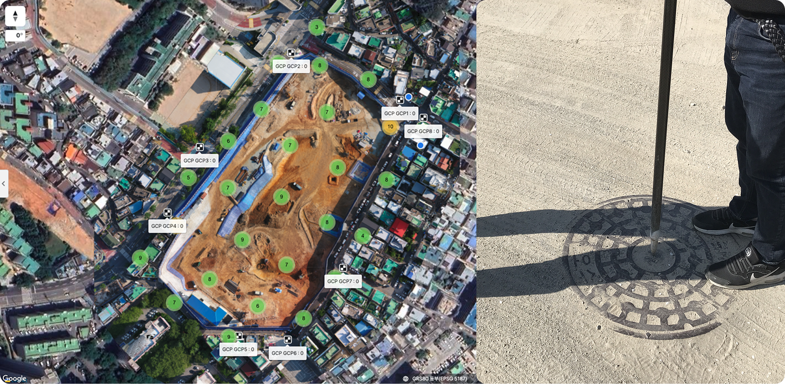
Aligning the reference point and the coordinate system comes first. Whether data is accepted as evidence for settlement often depends less on the capture or processing method than on whether the standards are properly interlocked.
When these standards are properly aligned, the results will be easily accepted as evidence for settlement, regardless of the capture or processing methods used later.
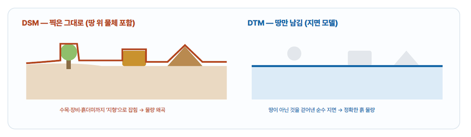
It is appropriate to verify progress quantities based on a DTM (Digital Terrain Model), which represents only the ground surface.
Terrain data generated by drones is fundamentally DSM (Digital Surface Model) . It captures the 'surface,' including structures, trees, equipment, and temporary soil piles on the terrain. If you calculate quantities in this state, obstacles are treated as 'ground,' which can lead to inflated or distorted volume estimates compared to the actual soil. DTMrepresents only the 'ground' after filtering out these obstacles, making it the standard for progress tracking where you need to see the actual shape of the soil.
In practice, a ground model is created through ground filtering and compared against the design elevation to calculate cut and fill volumes. While some may use a DSM as a substitute because the difference in values is not significant, this is not recommended for progress management. Simply verifying that the output is based on a DTM can reduce confusion in subsequent interpretations.
The value calculated via DTM is the net volume of the terrain, while the settlement quantity is the value converted by applying soil-specific change factors (coefficients). Therefore, it is important to agree upon and document which coefficients will be applied in advance. Since the volume of soil changes during excavation, transport, and compaction, it is difficult to treat the net volume as the settlement quantity directly. Soil volume change factors (conversion coefficients) are used to adjust for this.
Above all, the choice of coefficients and unit weights is not determined by a specific platform, but is a matter to be agreed upon by the site and relevant stakeholders. Documenting the agreed-upon values ensures there is a clear basis for reference should any discrepancies in interpretation arise later.
💡 For details on where and how to check the items discussed in this articlewithin the actual Meissa platform interface, please refer to the step-by-step practical guide (PDF) at the bottom of this page. This material focuses solely on 'where and how to check the data' and does not cover site-specific decisions such as coefficient values or settlement agreements.
While a single finished surface only shows the 'net change,' what is needed for settlement is the 'actual volume of work moved.' Because some materials disappear from the surface as they are covered by subsequent processes or hauled away, rather than relying on a single surface at a specific point in time, a method of accumulating the entire process day by day is required to preserve the data.
A prime example is replacing unsuitable soil (backfilling). When unsuitable soil is excavated (cut) and replaced with high-quality soil (fill), the finished surface looks almost identical to how it did before construction, making the net change appear close to zero. However, the "amount excavated" and the "amount filled" are separate work items and separate billable quantities, even though both disappear from the final surface. In this case, you must photograph the excavated state before it is covered by backfillingto ensure there is evidence for both quantities. The same principle applies to sections where cutting and filling occur simultaneously.

In sections where bedrock is exposed,the process is reversed: it gradually appears, is broken up, and is then hauled away. By periodically photographing the site (daily, if necessary) while it is exposed to capture the "surface" for each day, and then stacking these surfaces chronologically to calculate the volume between them, you can reconstruct the shape and volume of the material that has already been hauled away.
In both cases, the key is capturing the process as data before it disappears.This is why the continuity of photography is so important. By securing the site status just before construction begins, maintaining weekly scheduled flights, and sharing excavation, backfilling, and hauling schedules in advance, you can ensure the data remains uninterrupted. Mayson focuses on securing this accumulated site status as level data, while leaving the judgment of values (such as rock classification or boundaries) and the agreement on quantities to the site team.
Rather than choosing a single value, it is safer to cross-verify multiple calculated values and document the process as evidence. Comparing multiple values and building a record of the rationale behind them — this is the practical meaning of using drone earthwork data as a basis for settlement.
There is one principle that ties these five points together. Before generating numbers, you must first establish the conditions (standards, agreements, and records) that will serve as their foundation. Aligning reference points and coordinate systems, verifying progress based on DTMs, agreeing on soil volume change rates, keeping cumulative records of hidden quantities, and cross-referencing calculated values are all practical applications of this principle. This preparation, which must precede the actual flight, ultimately determines the outcome of settlement negotiations.
Maysa provides RTK drone and GCP-based surveying, DTM-based progress verification, and deliverables ready for immediate practical use, such as earthwork volume tables (.xlsx) and cross-section drawings (.dwg). For sites with challenging surveying conditions, we also offer professional surveying services.
We have compiled a practical guide below, centered on screen captures, to show you how to implement these five points within our platform. Please check it out via the banner below.

